Technology
SIMULATION BASED MODELING TOOLS

ITE State-of-the-Art Engineering Tools
- Digital Twins for Naval Ship HM&E and DC Systems
- Engineer Digital Mock-Up (eDMU)
- Virtual Reality.
- CAD & Computer Aided Engineering (CAE) Data Exchange
- Process Design
- Design Verification & Validation (V&V)
A Digital Twin for Naval Ship’s HM&E Systems Lowers Life Cycle Cost
The digital twin allows the USN and Shipyards to have a complete digital copy of the ship’s HM&E systems, from design, development, construction, and through the end of the ship’s life cycle.
Electronic Digital Mock-Up (eDMU)
Based upon the Howden Engineering Suite, Technical Readiness Level (TRL-9) technology the Digital Twin of the HM&E and DC systems also enables the Engineering Digital Mockup (eDMU) for Ship Building that Lowers Cost and reduces schedules.
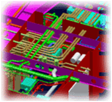
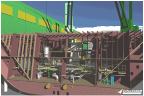
The eDMU integrates CAD systems – (Does it Fit?) with Computer Aided Engineering Systems (CAE) – (Does it Work?) coupled with Ocean Environment Models and Virtual Reality technology to provide the realistic and accurate eDMU.
The eDMU of the Ship’s Hull Mechanical & Electrical (HM&E) plant provides life cycle support in the maintenance and troubleshooting of HM&E system faults and Modernization throughout the life of the ship.
Unlike a Physical Mockup that is expensive to construct and maintain, the eDMU is easily developed as a byproduct of the Engineering Design Process and easily maintained via digital updates.
ITE can provide CAD and CAE Integration Software & Training to users that integrate CAD and CAE systems.
Howden Engineering Suite Formerly Simsmart Engineering Suite
Over the past 25 years the US Naval Sea Systems Command, Shipyards, and Marine Engineering companies have continued to improve their engineering design processes.
The first electronic design tool to gain wide acceptance was 2D, followed by 3D-CAD. Clearly, it is essential to verify that all the systems (fluid, gas, electrical, HVAC, etc.) fit into the spaces, without conflict, while maintaining weight and balance. However, CAD systems do not confirm that the systems “work” correctly. Therefore, physics-basedsimulation-based design (SBD) engineering design tools were developed to verify, individually, fluid, gas, and electrical process dynamics.
As 3D CAD systems are now commonly understood and used, marine engineers are placing increased focus on the SBD engineering requirement to verify that the HM&E and Damage Control systems “work” correctly and are sized properly before releasing drawings for production.
For more than twenty years, the engineering tool of choice for this task has been the Simsmart Technologies Inc.’s (now part of Howden) software, “Engineering Suite”. This is because Engineering Suite is the only TRL-9 SBD tool that integrates multi-discipline design of fluid, gas, HVAC, electrical, and most recently two-phase flow systems into the same digital design environment. These flowsheets can be compiled into run-time so that the total system performance can be validated in real time across multiple disciplines, ship wide to observe the system performance of the various HM&E systems.
The Engineering Suite design tool is currently in use by NAVSEA, the major shipyards and marine engineering firms. It is the only SBD process engineering tool in use in common across these organizations. Engineering Suite has been selected in each case following a competitive evaluation.
Technical Level 9 – Engineering Suite
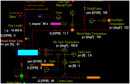
Engineering Suite is an integrated, multi-discipline, marine engineering design tool used by marine engineers to produce electronic marine process flowsheets to conceptualize, verify and complete their designs of fluid, gas, HVAC, electrical and engineering control systems. This is accomplished by selecting library object icons (pipe, pump, valve, sensor, duct, motor, wire, circuit breaker, controller etc.) from stencils and placing these objects on to flowsheets. The difference is that these Engineering Suite object icons are ‘smart’ Process and Instrumentation Diagram (P&ID) icons. Each icon brings its own completely encoded first principle physics equations on to the flowsheet. The engineer has then to only size, line up and connect objects that make up the system.
Engineering Suite software first verifies that the system components are compatible and then subsequently compiles the completed system into a run-time environment on the original flowsheet. The engineer can “turn on” his systems and run them as if the system(s) were on the ship itself, complete with control panels and consoles if desired. The engineer can stress test the system(s) to verify that they work under all conditions as part of the verification process. All system data reports and results can be printed out from Excel.
If the first design does not meet the customer requirements then the flowsheet can be reopened quickly, and object icons re-parametrized, added or deleted. This greatly facilitates “rapid prototyping” in the scope of an engineering design cycle.
More importantly, the engineering design (intellectual property) is now captured in a standard electronic format that can be connected to other systems being designed for the ship (at this or any other Engineering Suite equipped facility). These connections can be progressively aggregated until the entire hull, mechanical, electrical and damage control (HME&DC) system has been designed and dynamically verified in the Engineering Suite environment. Through Dynamic Data Exchange (DDE), Engineering Suite flowsheet data can be fed in real-time to Excel (or other DDE compliant software) spreadsheets for tabular and graphical evaluation.
In addition, thru the use of Application Programming Interfaces (API’s), Engineering Suite flowsheet data can be linked to Combat System components to evaluate and confirm the operation of these components to answer questions such as the impact of extreme high sea water temperature on the ship’s chilled water system. The same applies to extremes of air temperature on the ships HVAC systems.
Engineering Suite flowsheets have become a standard way of capturing HME&DC designs because Engineering Suite permits verified sub-systems and systems to be exchanged and, as appropriate, be aggregated to become complete ship systems.
Once validated with the actual Ship’s HME & DC systems these models can be provided to Training System Developers to lower the cost of creating training systems. In addition these models can provide the built-in decision aids for hull and HM&E systems to deliver readiness status in real time, during normal operations or the new status following system failures or combat damage.
Engineering Suite Ship Design Phases:
- New System design and re-scaling of previous designs
- Systems verification
- Engineering operating concept and operational doctrine
- Engineering casualty and damage control doctrine
- Manpower versus automation requirements
- Engineering control system design and operation
- Dock & Sea Trials used to validate the total ship model and ship systems as built
Digital Twin and Engineering Suite Ship Post-delivery Phase (re-use of the validated SBD models):
- Shore Based and Embedded on board training
- Engineering plant operational decision aids and/or battle decision aids
- Run the Engineering Suite model in parallel with the real system and compare outputs.
- Engineering and Damage Control casualty analysis
- Condition based maintenance and readiness assessment
- NAVSEA-Fleet Distance Support
- Documentation and validation of future Ship Alterations
- Confirm operation of Mission Modules before ship installation
- Capture ship design “intellectual property” for scalable re-use.
- Use as a common “method of exchange” for HME&DC systems engineering designs.
- Reduction in engineering hours
- Electronic design data exchange with CAD tools
- Combined “working” P&ID process flow diagrams with the Compartment & Access Drawings
More than twenty classes of USN and international naval ships& submarines, including Australia, Canada and Korean ships and submarines have one or more systems modeled in Engineering Suite.
Engineering Suite Models:
- LPD-17Design and Production models
- Firemain
- Mogas
- Chilled Water
- Auxiliary Sea Water Cooling
- Nitrogen Inerting
- Fuel Fill & Transfer
- Air Deballasting
- Ballast & Deballast Hydraulics
- CG47 class AAW upgrade &modernization
- electric plant (12,500 object icons) for real time analysis of electrical loading behavior.
- Chilled Water System
- Firemain
- Auxiliary sea water cooling system
- DDG-51 Battle Force Tactical Trainer (BFTT)
- CVN Firemain (17,000 object icons),
- NASSCO BP Oil Tanker
- Cargo Oil Piping System
- Ballast System
- DDG 1000
- Virginia Class Submarine
- Canadian Victoria Class Submarine
- HVAC and liquid systems comprised of 5800 parts across 121 flowsheets.
- Indigenous conventional submarine projects for ROK Navy